
Reverse Engineering a GDS file to its functionality
Contents:
Table of contents:
- Warmup
- Puzzle
- Netlist Extraction
- Basic Analysis
- DANA
- Observations
- Inferences
- Solving
- Finding the right input sequence for success
- Understanding the puzzle
- Easter eggs
Jane Street had released a challenge. It was about reverse engineering an ASIC given its GDS file. We were given a warmup GDS for an 8 bit adder to play with and the puzzle. This is the write up for it.
# Warmup
- Traced the netlist by hand to get a feel for the adder. I had made adders before, but using only AND, OR and XOR, this one used NOR, XNOR etc. so it didn’t LOOK the same initially.
- Tracked a few input output pairs, to bring the point home. It also helped with seeing how “conb” wasn’t used to store a constant value. That is, the constant being a specific combination of the gate highs was a first.
- Installed the right software tooling here. I need KLayout for viewing the GDS. I also needed the right skywater library to load it. Then installed HAL for visualising the running code on the netlist.
- Did some visual inspection of the GDS. This just means toggling the different layers, seeing what stays vs what goes, understanding the meaning of different layered representation, how transistors sit in the GDS as so on.
- I tried to do some timing analysis in HAL (I didn’t think about SAT solvers just yet) to see how the different ripple adder bits would arrive. Turns out they were arriving in chunks of 2 (i.e. 2 bits at a time), so the ripple carry was kind of mangled by an optimisation engine. I am still not 100% sure how that worked. I didn’t run DANA here, there wasn’t much reason for that since I was just exploring how things looked at that time!
- Verified the GDS to netlist tooling, ran it for the warmup a bunch of times to make sure the transistors are modelled correctly, and gates are according to the skywater library and so on. Verification was just making sure no nets are hanging, no unknown transistor combinations made it through and so on.
# Puzzle
# Netlist extraction
Used the same code as from the warmup to get a netlist for the puzzle. Verification of the netlist was just checking for any floating pins. I used the sky130_fd_sc_hd__tt_025C_1v80_hal.lib file for extraction. It’s unlikely that this didn’t have a module that the actual puzzle did. And it worked on warmup well.
I have focused more on the puzzle logic itself rather than the quirks of extracting netlists. One reason for that is the skywater labels survived in the GDS (thankfully) so technically, the job become much much easier.
# Basic Analysis
Only VPWR and VGND were used for power rails; VPB and VNB tied to them.
- No second always on supply because there is no power gating
- No retention through power down (That’s what KAPWR is used for)
- No level shifters, means it requires just one voltage throughout
This just simplifies the circuitry.
A bunch of “tapvpwrvgnd_1” cells that just tie the VPB and VNB to the power rails. They have 0 transistors (so no logic).
Exactly one clk port
No icg(integrated clock-gating)/dlclk cells
This means that all flips flops are operating with the same clock signal, there is absolutely no disturbance there. Hence, all FFs toggle at each pulse of the clock (storing or not storing depends on enable).
No memory macros. This means no KBs of data and we don’t have to worry about any read/write protocol logic which might be lurking around.
No cross-coupled NANDs or NORs, so all FFs are either dfrtp, dfstp or dfxtp (according to skywater naming). There isn’t any hidden FF logic anywhere.
Counting the number of elements we have for different subsets
flip-flops: 92
muxes: 21
and_or: 298
xor_xnor: 50
inverters: 25
buffers: 1
aoi_oai: 192
tie_cells: 6
tie_cells in this case are constant holders. The “conb” cells.
We can do a bit of clearing here,
- Taps + decap + diode -> Removed all of these
- Consolidated all clkbuf into one clk line. The multiple clkbuf were only increasing the different randomly named nets. clkbuf is a no-op logic wise. Its job is physical.
# DANA
DANA is a Dataflow analysis tool for netlists. I wrote a blog about it too. Ran it with the following params:
Expected Register Size: 4, 8, 16, 32 (default 8, 16, 32)
Minimum Size of Group: 4 (default 8)
4 as well, because the number of flip flops to be 92 and 92 doesn’t fit nicely with powers of 2, the closest we can get is 11 registers of 8 bit, and 1 register of 4 bits, so that was my guess and hence I expected 4 FFs to also show up in a group. I had no prior to give to DANA.
The output was 18 registers. Below is a visualisation for that, where each block is one DANA module, and it lists its ID and size (the number of FF in that block). I arranged the diagram suggestively because at initial glances, it looked like I could make out the primary inputs and outputs. I was wrong, but it’s a clear visualisation nonetheless.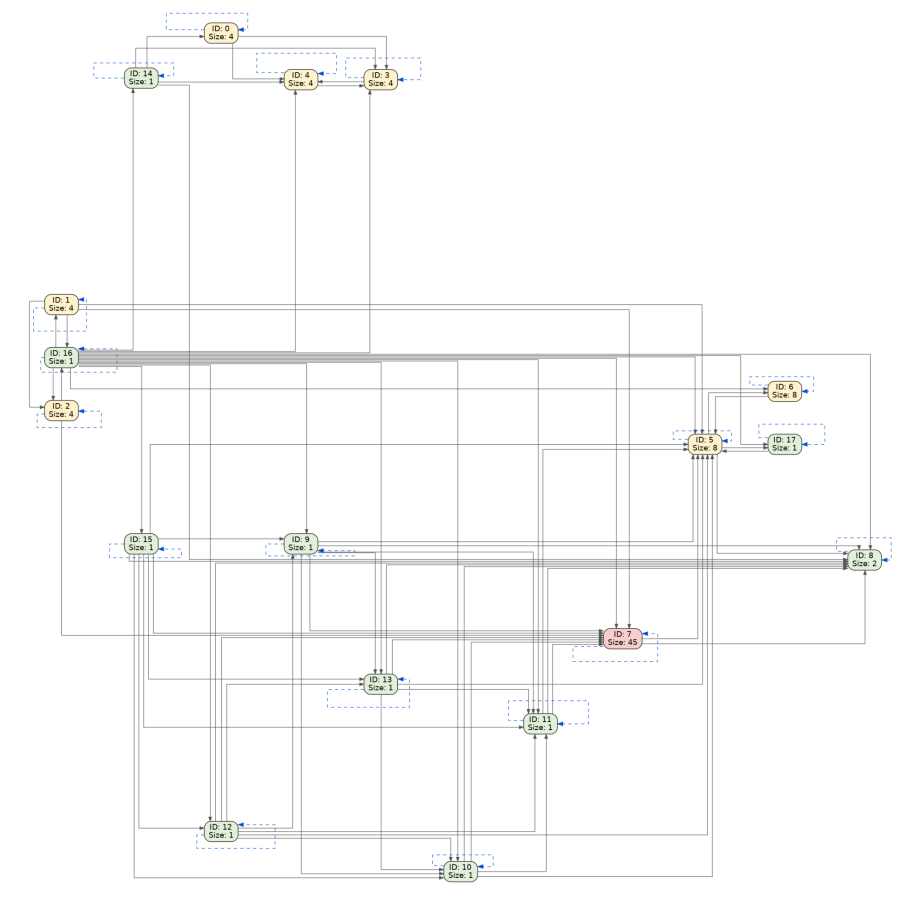
# Observations
- Group 16 is just 1 FF which feeds to every other (except 0). This might mean that 16 is related to the clk (a hypothesis, corrected in point 6 of inferences).
- Groups {15, 12, 9, 13, 10, 11} form a dependency chain (w.r.t. their predecessors) which is very interesting to note.

That is,
15 needs: 16
12 needs: 15, 16
 9 needs: 15, 12, 16
13 needs: 15, 12, 9, 16
10 needs: 15, 12, 9, 13, 16
11 needs: 15, 12, 9, 13, 10, 16
- Group 8 has no successor except itself. (It must be related to the primary outputs)
- Groups 0, 3 and 4 form a closed subgraph, that is, they are their own successors. This means nothing that they compute, ever goes outside.
- Groups 1, 2 and 16 also have similar interdependence.
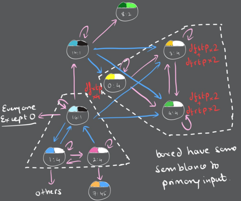
I assumed that these 5 (all except 16) might be related to primary inputs.
- All FFs in group 0 are dfxtp, which means they cannot be reset. (This is important because reading this register value gives the string as explained in the “Understanding the puzzle” section.)
- Groups 3 and 4 are 2xdfstp (resets to 1) and 2xdfrtp (resets to 0) each. Therefore, at reset conditions, these 8 FFs (if considered together as an 8 bit value) are holding one of $8!/(4!4!)=70$ possible values. They are determined, but their order is nothing we know.
- There is a group 7 which has 45 FFs in it. This is certainly an odd number of FFs to have, so we’ll have to be more careful about how this plays out.
- Traced group 8 to be the output for the success flag. Group 8 has 2 FFs but success is just 1 bit of value, so one of those two FFs must be holding the bit. We’ll get back to this when we analyse the functions leading to each group.
# Inferences
Now let’s talk about a few more inferences. Before that I ran a BFS on all primary inputs to see which FFs from which groups they are hitting. I haven’t included that data because it’ll be quite wasteful of space on its own, so I’ll explain all the important parts.
- We know that groups {15,12,9,13,10,11} form some sort of a hierarchical structure. This just means that:
$$Q15_{(n+1)} = f(Q15_n,\ Q16_n)$$
$$Q12_{(n+1)} = f(Q12_n,\ Q15_n,\ Q16_n)$$
and so on …
- Tracing the input “I” in HAL to see which FF it goes to, we get this
For I (Input)
flops reached: 58
group 4 : 1 flops [D x1]
group 5 : 6 flops [D x6]
group 7 : 45 flops [D x45]
group 9 : 1 flops [D x1]
group 10 : 1 flops [D x1]
group 11 : 1 flops [D x1]
group 12 : 1 flops [D x1]
group 13 : 1 flops [D x1]
group 15 : 1 flops [D x1]
Now this is interesting because all the groups from the nested structure are listed here. This implies that for group 15, it must get input “I” without reaching any other FF, so no combinatorial logic will have mangled the “I” that comes to group 15. I can say this with confidence because group 15 has predecessors as only itself and 16, and we have hypothesised that 16 is some “clk” kind of signal. (corrected in point 6)
This means:
$$Q15_{(n+1)} = f(Q15_n,\ Q16_n,\ Input)$$
$$Q12_{(n+1)} = f(Q12_n,\ Q15_n,\ Q16_n,\ Input)$$
and so on …
(Note how “I” doesn’t reach groups 0, 1, 2 and 3.)
- When I traced the functions for the group 15 (since it’s clearly the first one in the chain as it has all the others as successors), I found that the input to the D of the FF in group 15 is given by:
$$Q15_{(n+1)} = Q15_n \ \textbf{XOR}\ ((\sim Q16_n)\ \&\ \text{Input}\ \&\ \text{enable})$$
(Note: Traced out for a group here means that I picked one FF in there and went backwards to hit each combinatorial gate to see how its D value is affected. For one FF groups like all of these ripple carry ones, it just means tracing the group)
We find a similar pattern for the other groups in this chain as well:
$$Q12_{(n+1)} = Q12_n \ \textbf{XOR}\ (((\sim Q16_n)\ \&\ \text{Input}\ \&\ \text{enable})\ \textbf{AND}\ (Q15_n))$$
$$Q9_{(n+1)} = Q9_n \ \textbf{XOR}\ (((\sim Q16_n)\ \&\ \text{Input}\ \&\ \text{enable})\ \textbf{AND}\ (Q15_n \ \textbf{AND}\ Q12_n))$$
$$Q13_{(n+1)} = Q13_n \ \textbf{XOR}\ (((\sim Q16_n)\ \&\ \text{Input}\ \&\ \text{enable})\ \textbf{AND}\ (Q15_n \ \textbf{AND}\ Q12_n \ \textbf{AND}\ Q9_n))$$
…
The pattern seems to be clearly:
$$QK_{(n+1)} = QK_n \ \textbf{XOR}\ ((\sim Q16_n)\ \&\ \text{Input}\ \&\ \text{enable})\ \&\ (\textbf{AND}\ \text{of predecessors})$$
- This is like a ripple carry adder, where the carry flags are propagated. But this cannot be adding two numbers together since we don’t have a second number input with group 15. This means it can be a counter or an incrementation circuit.
- We can also note that the input must be high if it’s to be set.
- Then we also note that input “I” is DIRECTLY fed to group 15 (the LSB probably that starts the chain) without any FF in between. So, these groups operate directly on the input.
- Since, they take in “I”, and they become 1 when “I” is 1, the group seems to be incrementing at the count of 1 in “I”. That is, it counts the number of 1s in input “I”. Now that’s a good find because if we can compute from the success condition what this number should be, we’ll be closer to the solution!
- This also led me to believe that all these different groups can probably be one single register, that having 6 bits (I was wrong since we must add one more element to this, which I’ll do right next).
- Now group 11 also has group 7 (the 45 flop register) as its successor (along with 5, 8 and itself). 8 is the success FF (I am ignoring 5 because I don’t want to think about that right now, see “Understanding the puzzle” section for more details) so that means this chain DOES something directly to the success bits.
So, at least one FF from group 7 must be related to this ripple increment group of FFs. Turns out it’s just 1 FF only in group 7 which is connected to group 11’s sole FF.
grp 15:    {15, 16}
grp 12:    {12, 15, 16}                                  = previous + {12}
grp 9:     {9, 12, 15, 16}                               = previous + {9}
grp 13:    {9, 12, 13, 15, 16}                           = previous + {13}
grp 10:    {9, 10, 12, 13, 15, 16}                       = previous + {10}
grp 11:    {9, 10, 11, 12, 13, 15, 16}                   = previous + {11}
g270:      {7, 9, 10, 11, 12, 13, 15, 16}                = previous + {7}
Now we know that the groups: {15, 12, 9, 13, 10, 11, 7} each give one FF to (potentially) form a ripple chain counter or some sorts.
- Coming back to success, we’ll also trace out the functions for group 8. Since it has two FFs, I did it for each of them.
Both have similar structure
1582: f = (net_30 & (~net_607 | net_697)) | ( ... & ((~ net_449) & net_455) & ... )
1536: f = (net_713 & (~net_607 | net_697)) | ( ... & ( net_449 & net_455) & ... )
The thing is, net_713 was not referenced anywhere else in the netlist, while net_30 was, according to HAL, the same success net. So, I went with the 1582 FF.
Success = ((net_176 & net_177) & ((~net_204) & net_208)) & ((net_164 & (~net_174))
& (((~net_221) & (~net_235)) & ((~net_237) & (~net_245))) … (it has some 54 literals)
Now this has 54 literals, but a few of those are from the ripple carry groups. Since we know that it’s counting the number of 1s in the input “I”, if we find the value that the FFs in these groups hold, then we can have the right count of 1s in the input!
Success = ((g12 & g9) & (~g13 & g7_2)) & ((g10 & ~g11)) & (((~g7_1) & (~g5)) &
((~g7_3) & (~g15))) … (bunch of other stuff)
=> g12 & g9 must be 1 => g12 = g9 = 1
=> ~g13 & g7_2 must be 1 => g13 = 0; g7_2 = 1
=> g10 & ~g11 must be 1 => g10 = 1; g11 = 0
=> g7_1 = 0; g5 = 0; g7_3 = 0; g15 = 0
Therefore those 7 bits from the ripple chain are:
grp 15  | bit 0 = 0
grp 12  | bit 1 = 1
grp 9   | bit 2 = 1
grp 13  | bit 3 = 0
grp 10  | bit 4 = 1
grp 11  | bit 5 = 0
grp 7_1 | bit 6 = 0
MSB first we get a 7 bit number: 0010110 which corresponds to the decimal 22.
Cool. So we know that input “I” must have 22 ones.
However there are some 47 other constraints (that is, a 47 bit number, but like I have no reason to believe they will all be in a 47 bit register) that I didn’t write down, but we’ll have to check for all of those if we want success to be high.
- So, after this I was kind of lost, so I ran the function analysis on one FF of each group, and turns out the general formula for their inputs (n+1) is something like this:
$$Q_{(n+1)} = Q_n \ \textbf{XOR}\ b; \quad \text{with } b = c\ \&\ (\textbf{AND}\ \text{of predecessor FF outputs}); \quad \text{with } c = \sim Q16\ \&\ I\ \&\ \text{enable}$$
This means something pretty cool actually, because as soon as Q16 is set, c becomes 0, and $Q_{(n+1)} = Q_n$ at all times. So the machine has frozen! This just means that group 16 is actually a halt condition and not a clock. So my hypothesis was wrong.
- Once I knew that group 16 decides to halt the machine when it is set 1, then we can monitor that FF and keep adding inputs until it hits 1. Input “I” reaches groups 4, 5, 7, 9, 10,11,12, 13 and 15, and not 1, 2 or 16. Group 16’s halt condition is computed from groups 1 and 2, which never see input “I”. So, the halt condition is independent of the input, hence we can randomly throw in random bits without worry. Before that we need to create a simulation environment.
- We know all the gates and flops and the netlist. Simulation is moving the circuit forward, which is not that hard. We’ll just have to model all the different skywater library gates.
- I can create the sim, and send in random bits one by one, until we hit the halt condition (that is group 16 FF goes high). This happens exactly after 121 bits.
I tested this for multiple random sequences just to be sure. This implies that the input needs to be a 121 bit sequence.
# Solving
# Finding the right input sequence for success
At this point we know just one specific condition, that there should be 22 ones in that specific 7 bit register and there need to be 121 bits of input. There are $^{121}C_{22}$ possible combinations. This is not something we can brute force. That’s just considering a set of FEW literals. If we add more conditions, it just gets worse.
We know we can’t solve this by linear algebra (as a bunch of linear equations) because of the general form of $Q_{(n+1)}$. The AND terms make it non-linear. Otherwise we could possibly just throw everything into a huge matrix and do something there.
I mean, except group 15, which has no cascading AND terms, no other group will be linear, so this is NOT solvable via any cool matrix tricks.
So, we’ll have to rely on a SAT solver only. SAT solvers require CNF expressions (ANDs of ORs). These expressions need to be converted via tseytin transforms (circuit to CNF). Then the solver and the simulation are the same circuit, but the solver plays it in reverse.
Before that, since we know that there are 92 FFs, and input is 121 bits, then the circuit must be a transformation from these 121 bits to the final 92 bit stage. We know 54 of these 92 FF values (by backtracking success), and we want to be able to find anything about the 121 bits.
We also know that the initial state for all the FFs that affect success is 0, because they are all dfrtps. We’ll have to enforce an all 0 state, then run backwards, enforcing the 54 FF values that we know and then hand it over to the SAT solver.
- In this case, I was using CaDiCaL 1.5.3, I wasn’t sure if the version would matter anyway, so I picked from the middle of the pile.
- The tseytin transform and CaDiCaL increases the number of variables, but it makes analysis far easier, because we now have a stricter way to impose values. For example, for this clause:
$$\text{flag}_{t+1} = \text{flag}_t \ \textbf{OR}\ \text{detect}_t$$
Is expanded as:
$$(\sim \text{flag}_{t+1} \ \textbf{OR}\ \text{flag}_t \ \textbf{OR}\ \text{detect}_t) \Rightarrow 1$$
$$(\text{flag}_{t+1} \ \textbf{OR} \sim \text{flag}_t) \Rightarrow 2$$
$$(\text{flag}_{t+1} \ \textbf{OR} \sim \text{detect}_t) \Rightarrow 3$$
Now, if we enforce a condition like $\text{flag}{121} = 0$; then from clause 3, we know that $\text{detect}{120}$ MUST be 0 (cause by definition, clause 3 is true), and from clause 2 we know $\text{flag}{120}$ MUST also be 0. We can do the same thing for $\text{flag}{120}$; enforce a condition and find something about $\text{flag}_{119}$ and so on.
Another good thing about this is, a lot of the clauses ended up being something like this:
$$(\sim X \ \textbf{OR} \sim Y) \Rightarrow \text{both X and Y cannot be True at the same time.}$$
$$(\sim X \ \textbf{OR} \sim Y \ \textbf{OR} \sim Z) \Rightarrow \text{At most 2 of the three can be true at the same time.}$$
So, running the SAT solver, we’re able to get an answer. It’s this 121 bit string:
0000000101010000100000000000010101010000000000001010000001000001000000100000101000010000000100000010000010010001010000000
This is supposed to be fed at each cycle, with enable high so that all FFs are able to record the right values.
# Understanding the puzzle
1. The 45 bit group 7
There were a few signs about the “kind” of logic we were dealing with here. The first telltale sign was group 7’s 45 FFs. Initially when I was just playing with the puzzle, I tried to see which FF would respond to which bits in the input stream. So, of the 121 bits, I indexed it (an idea I explained later in this section too) from 0 to 120, ran 121 copies of the simulator with the i’th bit as 1 and others 0 for all i.
The result of this was surprising, because every FF responded to some position of 1, except 22 FFs in group 7 (i.e. 22 FFs in group 7 turned high for at least some position of 1 in the 121 stream, 22 remained zero). Recalling that 1 FF in group 7 was part of the ripple chain adder, I assumed the remaining 44 would at least be a collective thing, but maybe they weren’t.
Also recall that I mentioned there were some 54 literals in the success function which needed to be exact. Of those 54, we separated the popcounter (7 literals/bits) and found the value to be 22. Of the remaining literals 44 came from group 7! What’s even more exciting is that it required 22 to be high and 22 to be low.
And by twist of fate, the 22 that went high in our case (of scanning with a single one), were the ones that were REQUIRED to be low for success to be driven, and the ones that didn’t respond, should’ve been high!
Since the initial state of the machine is all 0 (for the success path), the FFs that never went high for single values of 1 in the bit stream, MUST flip somehow. So, I tried 2 values of one at a time because it clearly needs more than 1 mark to be high. There are $^{121}C_2 = 7260$ possible combinations and I tried them all. And this worked, it flipped those presumably dead FFs in group 7.
This means that group 7 was completely annihilated by DANA. It really should have assigned 1 FF to the ripple popcounter, 22 and 22 to two separate regions!
I didn’t have to go higher than 2 because it worked here. So I stopped. If it didn’t I’d have tried 3 and 4 too (though 44 doesn’t cleanly split in 3).
2. The inverse counting for FFs to 1s in input
I already made the check for which FFs respond to which 1 in the input (just one 1). If we look for how many positions did FF number i respond to, we’ll get all the positions for a FF to respond (I mean, that was a pretty obvious statement).
Another surprising thing, of the 22 FFs in group 7 that were supposed to be low to drive success (and which went high during the initial 1 bit probing round), 11 FFs had the values {14, 21, 7, 5, 28, 8, 11, 9, 6, 8, 4}.
For the other set of 11 FFs, it’s even more interesting. Their set looks like {11, 11, 11, 11, 11, 11, 11, 11, 11, 11, 11}. And if we pick one flop in this family of 11 and see WHICH positions of 1s does it respond to, we get {3, 14, 25, 36, 47, 58, 69, 80, 91, 102, 113}.
That’s a lot of 11s.
The first set sums to 121 and so does the second one. This means that these 11 FFs together (for both sets) respond to all possible positions of 1s.
Each FF in the second set responds to only 11 different positions of 1s in input AND these 11 positions are all placed 11 bits apart.
If we write out the positions of 1 that the second set responds to:
{0, 11, 22, 33, 44, 55, 66, 77, 88, 99, 110}   column 0
{1, 12, 23, 34, 45, 56, 67, 78, 89, 100, 111}  column 1
{2, 13, 24, 35, 46, 57, 68, 79, 90, 101, 112}  column 2
{3, 14, 25, 36, 47, 58, 69, 80, 91, 102, 113}  column 3
...
{10, 21, 32, 43, 54, 65, 76, 87, 98, 109, 120} column 10
That’s all the 121 elements accounted for.
Note: I have written them suggestively in hindsight but at the time of solving, I didn’t know they could form columns
3. Group 5
I’ll take a small paragraph to explain what group 5 was doing now. So, I mentioned in point 4 of inferences that I was ignoring group 5 from the ripple chain. I could’ve assumed that at least 1 FF from group 5 is also a part of the chain but I didn’t.
The reason for that is group 5 has no FF which extends the dependency chain the way group 7 FF does. I showed the diagram in the same section which explains how that dependency was matched in group 7.
But group 5 is important because it shows us in the success function. So far we have seen that success depended on 54 literals:
- 44 of those are from group 7
- 22 should be set high
- 22 should be set low (11 + 11 structure explained above)
- 7 from the popcounter
- 6 from the groups {15, 12, 9, 13, 10, 11} and 1 from group 7 (g270)
- No FF from group 5 extended the chain
That leaves 3 FFs, and group 5 tries to fill that gap. It’s not relevant to understanding the puzzle, but I just thought I should mention it so that we’re on the same wavelength.
4. Bringing it home
Now we have numbers and partial information to play along with:
- 121 is $11*11$
- 22 is the number of stars there would be on an 11x11 grid for a 2 star battle.
- The solving part above kind of enforces the rules of the game!
- Two different ways of dividing 121, with {14, 21, 7, 5, 28, 8, 11, 9, 6, 8, 4} and {11, 11, 11, 11, 11, 11, 11, 11, 11, 11, 11} from above.
- If we split the 121 sequence we got into 11 bit chunks, each of those has only 2 ones.
At this point, I gave all this information to an LLM because I had no idea what all this means. And it very easily told me that this is a game called starbattle (2 not touch) on an 11x11 grid. I had never played this before, so I went online to play a few.
This means that the entire puzzle had been about finding the right pattern to finish a starbattle game! Wild.
My next question how it enforces the rules w.r.t. an entire square of neighbours not just what came before. How does it “think ahead”?
I dug somewhat into this, not too deep though, but the rules had been encoded to avoid this problem of looking ahead. The two “rules” for example is one example of how it used bits in sequence to enforce some rules. It’s a very clever idea, I hadn’t thought of something like this before.
To make it clearer:
Let’s say that we’re feeding out 121 bits one by one. We’ll index the bits as 0, 1, 2 …120. Now let’s imagine placing them on the grid one by one. For a bit at index T, let’s say it’s placed at a cell t.
Cell t is at position (r, c) and it has eight neighbours. Four of them arrive before T does in the input stream at positions (r-1, c-1), (r-1, c), (r-1, c+1), and (r, c-1). Four arrive after. The puzzle is trying to use these 4 to enforce rules about the whole neighbourhood.
The indices of its 4 previous neighbours MUST be: T-12 (the top left; (r-1, c-1)), T-11 (the one right above; (r-1, c)), T-10 (the top right; (r-1, c+1)) and T-1 (left of it; (r, c-1)). This means, for each cell, to verify the rules for it, the puzzle must be having a 12-bit window.
I am pretty sure the mechanism is already revealed to me, but I didn’t really spend more time on this.
Now another curious thing is the O[7:0] bits of output. We need to know what it’s holding when we pass in the right sequence of inputs. If we trace the functions for these output bits, we get:
$$\text{group 0} \Rightarrow \text{213 gates of logic} \Rightarrow \text{O[7:0] pins}$$
That’s interesting because we have already noted that group 0 doesn’t take values from anyone apart from itself and group 14 (which in turn takes it only from group 16 apart from itself, so it’s like a delayed halt switch so to speak). And we know group 0 cannot be reset.
Since group 14 only fires AFTER halt (group 16), the group 0 would be 0000 for the entire time we feed the 121 bits of the correct sequence. This means that group 0’s and in turn O[7:0] output doesn’t even depend on the correct sequence because it only starts once the FFs freeze. (edit: I was wrong here. It does depend!)
If that’s the case, then we can just feed in all 0s to the machine, go over the 121 bit halt, and run a few more cycles to see what O[7:0] produces. (edit: If we do that, we get “TRY AGAIN” which is what I noted as an easter egg later)
If we consider O[7:0] to be a BYTE of output, then we know that we’ll be getting 16 bytes unique bytes at max (since group 0’s four FF can have $2^4=16$ unique bytes). This made more sense because trying to decode them as individual bits led me nowhere. Doing this however (with the correct bit sequence), gave the string:
(* TWO STARS *)
The hint that “There is one section of the design that is used to generate the output but does not affect the [success] output. You can safely ignore it for the initial reverse-engineering steps.” turns out to be for the groups 0, 3 and 4 that we cut off before.
I also wanted to see what the puzzle looked like. This is an interesting problem because the logic has been entirely baked into the combinatorial gates. We’ll have to think about what boundaries really mean then.
This is an inverse problem. Can we go from a two star solution to the boundaries given inverted rules? Actually that’s not a bijective mapping, so there are many possible solutions to the inverse problem and not a unique one. I tried to find some more proofs for these problems but that was me getting sidetracked.
To solve this problem though, we don’t really need to define boundaries from the input bits, we can simply take it from the puzzle itself. I assumed that the two different ways of splitting (the 11 sized registers I talked about before) were clearly columns and regions.
So, I took the region set, and took an 11x11 grid. I knew which FF goes where thanks to the second set of 11 FFs from the above analysis. This is how it came to look:
AAAAABBCDDE
AAFAABCCDDE
AAFBBBBCCDE
AAFBGGGECCE
FAFBGEEEEEE
FFFBGGGEHHH
BBBBBBGEHII
BJJJGGGEHII
BJJKEEEEHII
BBJKKEEEHHH
BJJKEEEEEEE
Now we can just draw lines at the boundaries (where two neighbouring cells have different letters).
# Easter Eggs
“PER ARENAM AD ASTRA” (from sands to stars) written in Morse in the puzzle GDS.
I thought it to be some internal routing at first (found this while solving the puzzle not after) because it was labelled “internal”. Then I found that 200/0 is a text layer and nothing that goes here is fabricated. So, putting anything here must be a choice by the designer on purpose.
I had LLMs give me a script to run in the python console to find the distances between them (because I didn’t know it was morse just then, I thought it might have to do with the distance too).
Distances were in a ratio of 1:3. The exact values were kinda weird.
Anyways, it didn’t cross my mind that a dash is 3 dots in succession on radio. I zoomed out and it started to look like dots and dashes so then it all clicked together and I was able to get the text.
“TRY AGAIN” present in the example_inputs.vcd waveform, byte output of O[7:0].
I actually tried this AFTER solving the puzzle because the blog mentioned there are some easter eggs in the repository as well and I hadn’t even opened the sample VCD.

I also noticed that the first byte appears after exactly 250 clock pulses (I just hand counted so I might be off here). And the total number of input bits given to the machine was only 88 ($11*8$) which I know in hindsight is not enough to print the actual string we need.
JSC visible in the grid layout for the star-battle
I was just curious to see what the puzzle even looked like. Got into rabbit hole of polyomino reduction and confluence trying to figure out some proofs for 2 not touch.
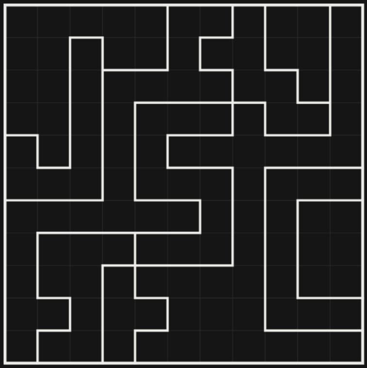
So that concludes the writeup. I wrote a complementary post on shape algebras for polyominoes for fun. You can check that out here.